6. May 2020
|

The cylinder deactivation on a diesel engine has showed potentials on the one hand side to further reduced pollutant emissions, while on the other hand to gain some fuel economy in parallel. This has been demonstrated by several investigations in the past. Nevertheless, a static deactivation of half of the cylinders is limited by their operation range. An additional dynamic deactivation of several cylinders delivers further degrees of freedom that could provide an extension of the cylinder deactivation operation range.
The authors have used different simulation tools such as 1D steady-state engine process model and transient mean value model to represent the possibilities of a dynamic cylinder deactivation on diesel engine applications.
A state-of-the-art diesel engine for passenger cars (PC) and medium duty (MD) truck applications have been used for the investigation program.
For the PC applications a 2.0 l 4-cylinder diesel engine with a single stage boosting system and a compression ratio (CR) of 15.5 has been considered. Further engine applications have been an advanced exhaust gas recirculation (EGR) system (uncooled high and cooled low pressure EGR path) and a 2000 bar fuel injection system (FIS). It has been decided to investigate two different vehicles, a C segment vehicle, as well as a compact SUV. Those have been equipped with a 7- and 8-speed dual clutch transmission (DCT). The exhaust aftertreatment system has installed a closed-coupled DOC, SDPF as well as a passive underfloor SCR. All EATS components have been used as aged system. The cycle investigations have considered the standard WLTC and a RDE operation.
The MD truck has been powered by a 7.7 l 6-cylinder diesel engine. The air path has a standard wastegate turbine (WG) boosting system together with a cooled HP-EGR system installed. The combustion system has considered a 2,400 bar FIS and a CR of 17.7. A state-of-the-art EATS based on closed-coupled DOC, DPF and SCR has been installed. For the MD truck application, the WHTC has been considered.

1D engine process simulation model
The commercial 1D engine process simulation software GT-SUITE has been used to investigate the thermodynamic reactions of the different exhaust gas heating strategies. The 1D engine model has considered the entire engine configuration, such as the boosting system, the air and exhaust path, the EGR path (high pressure and low pressure) and combustion chambers. The burn rate of fuel combustion has been implemented through profile arrays from several engine operation points of the entire engine operation range. Those have been generated by a standard 0D approach of cylinder pressure analysis of steady-state experimental engine measurements. The entire EGR control of the model has been modified from a mass flow control to an oxygen concentration control. The fuel injection pattern and rail pressure as well as boost pressure set points have been kept constant.
This 1D model can operate in the entire map range, and allows simulation throughout the entire engine operation range. Standard PID-controllers have been used to control components like EGR valves or turbocharges in order to regulate EGR rates or boost pressure under steadystate investigations. Finally, a sub-model for engine-out emission predictions had been added to the engine model. This uses the physical correlation approach of in-cylinder O2-concentration to predict engine-out NOx and soot emissions. Thus, transient effects on emission production have been considered, which usually occur at dynamic engine operation. In addition, HC and CO emissions have been implemented by steady-state maps which dependent on engine speed and load. The approach describes the standard at FEV and has been used in the past. To obtain an accurate result, the 1D model has been validated to surrogate data. The accuracy of boost pressure showed a deviation of maximum 1 percent. The calibration level of the emission models were more challenging and provided a maximum deviation of 5 percent.
Map calibration for considered heating strategies
To investigate the exhaust heating potentials of the different exhaust heating strategies within the mean value powertrain model (MVPM), the baseline engine-out maps have to be adjusted, based on the results of the 1D model simulations. For this purpose, differential and factorized maps have been generated and added incorporated into the base engine maps. Together with the differential and factorized maps, a new engine calibration with a specified exhaust heating strategy has been considered.
Mean value powertrain model
The FEV Complete Powertrain Simulation Platform, a precursor of FEV’s advanced VCAP calibration platform was utilized in this study. The powertrain model has integrated five main sub-models for boundary/ambient conditions, vehicle settings, transmission, engine and the aftertreatment system. The boundary/ambient condition sub-model described the different road conditions, emission test cycles and different driver behaviors. Inside the vehicle model the rolling resistance as well as road influence, aerodynamics and gravity were considered to model vehicle longitudinal dynamics. The main transmission and driveline components were modelled with ideal torsional systems, subjected to a distinct efficiency at different oil temperatures. Based on those sub-models, the main objective was to calculate the required inputs for the engine, mainly actual engine speed and load request. The engine model provided than on the specific operation point the corresponding engine out conditions, which were described by calibration maps at different coolant temperature.
Selective cylinder deactivation by Dynamic Skip Firing
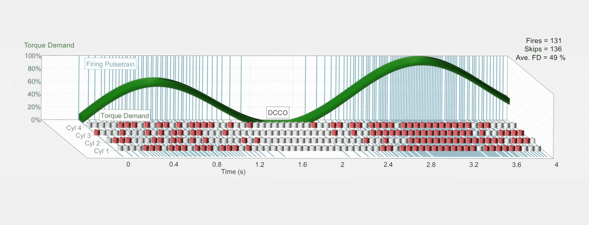
Dynamic Skip Fire (DSF) is an advanced cylinder deactivation technology. A DSF-equipped engine has the ability to selectively deactivate cylinders on a cylinder event-by-event basis in order to match the torque demand at optimum fuel efficiency while maintaining acceptable noise, vibration and harshness (NVH). To illustrate this concept, Figure 1 shows an example of DSF operation in a four cylinder engine. A varying torque request is shown in green, which results in cylinders being fired (red) or skipped (grey). The combined firing pulse train for all four cylinders is in blue. As torque demand increases, the density of firing cylinders also increases. When torque demand is zero or negative, no cylinders fire. This is termed DCCO, or deceleration cylinder cutoff.
The evaluation process has been substituted into two tasks. The first task has dealt with the steady state simulation investigations of the different heating strategies by means of 1D engine process models. Whereas the second task has focused on transient cycle investigation.
Analysis of steady state 1D engine process simulation results
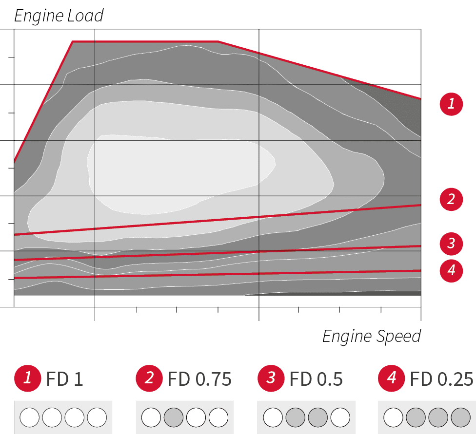
The 1D steady-state investigation have been obtained for partly loaded operation. Those investigations have been done underfour different fire density (FD) levels, where 1 indicates full cylinder operation. A FD of 0.25 is equal to a single cylinder operation out of this 4-cylinder engine. The steps in between are defined as 0.75 and 0.5.
The engine operation at a FD below 1 has led to an anomalous turbocharger operation due to the changed exhaust gas dynamics. Therefore, reduced boost pressure levels have been achieved and resulted in a limitation of the maximum engine load operation. Figure 2 shows a schematic of maximum engine operation loads that can be achieved at different FD levels.
Since the deactivation of one or more cylinders, the load at the remaining fired cylinders have been increased to hold a constant engine power output. The increased inner load has provided a higher exhaust temperature at a higher engine efficiency. Figure 3 summarizes the relative simulation results at a FD = 0.5 of engine efficiency improvement by BSFC and absolute exhaust temperature increase in the lower part load area. It can be seen, that FD of 0.5 has provided a fuel consumption benefit of 15 percent in average in the shown operation area. At the same time an exhaust temperature increase of almost 130 K at 3 bar of BMEP has been achieved in comparison to a 4-cylinder operation.
Additionally to the mentioned advantages other effects have occurred by a steady-state cylinder deactivation. On the one hand a reduction of the exhaust mass flow rate has obtained by deactivating cylinders. Hence, also a lower emission engine out mass flow rate has been achieved. While this has delivered, on the other some degrees of freedom to lower the steady-state EGR calibration to keep the same NOx engine-out mass flow rate compared to a 4-cylinder operation.

Evaluation and assessment of transient MVPM simulation results
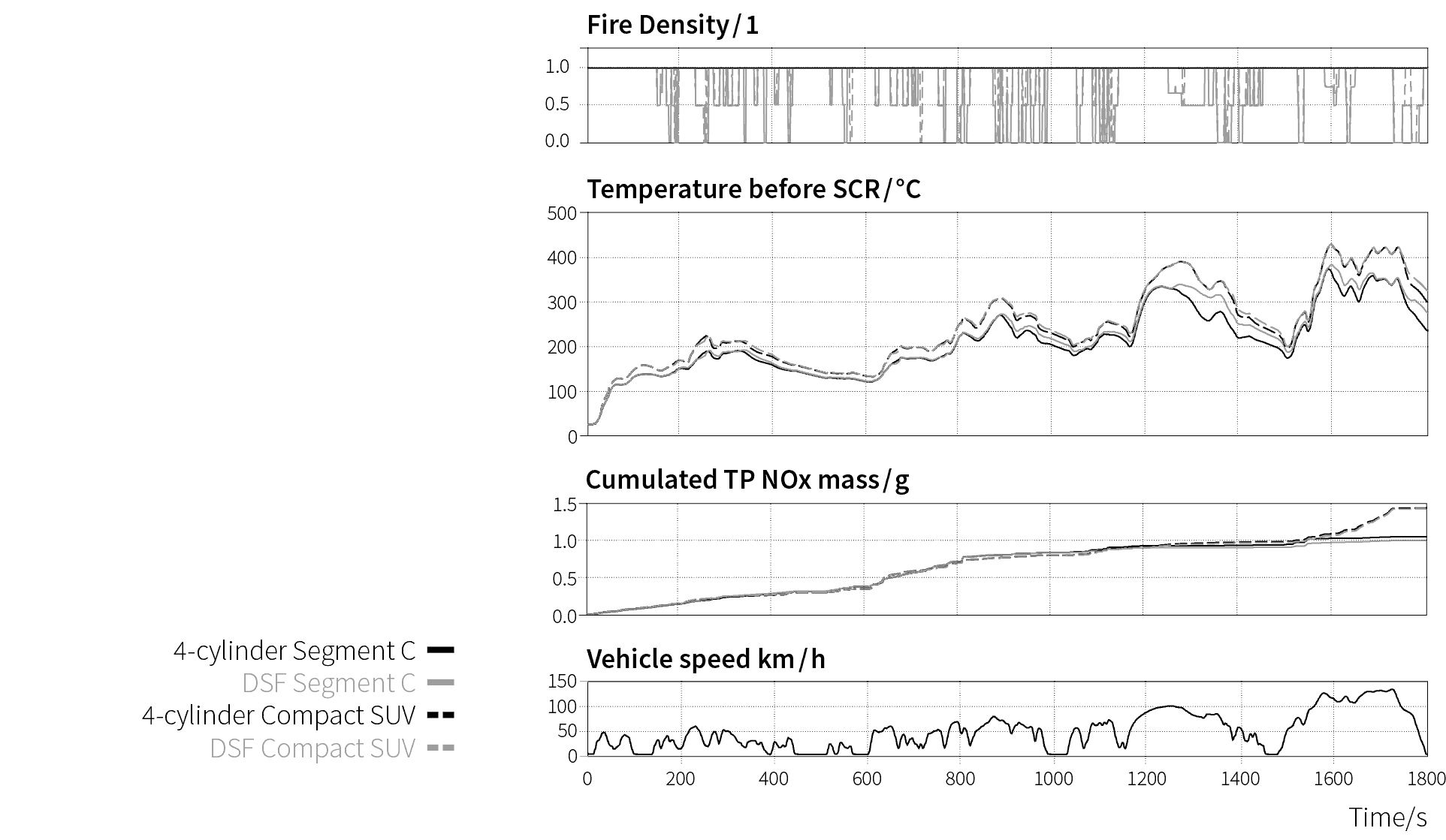
To determine the impact of DSF on relevant cycles, the WLTC and RDE were simulated for the PC application, and the WHTC was simulated for the MD application. Figure 4 shows transient results of C segment and compact SUV application over WLTC. It depicts the fire density, exhaust temperature upstream SDPF as well as the cumulated tail-pipe (TP) NOx emission.
The WLTC begins at an ambient temperature of 23 °C. A minimum coolant temperature limit of 60 °C is imposed to represent hardware constraints, and effectively eliminates DSF operation until 140 seconds. The exhaust temperature traces upstream SDPF have showed only slightly increase after cold start and warm-up phase, due to the thermal mass of the DOC. Afterwards, an exhaust temperature increase by around 20 K has been achieved under DSF operation at segment C vehicle. That increased exhaust temperature has improved the NOx conversion of SDPF and dropped the TP NOx emission down to 43 mg/km. It represents a reduction by
4.4 percent compared to the 4-cylinder operation of segment C. Additionally, these improved results have been achieved with a benefit in CO2 emission by 1.5 percent.
The results of compact SUV have showed a lower NOx reduction potential by DSF operation. This heavier vehicle application has led to a higher engine operation with an increase exhaust temperature level. Furthermore, the DSF operation has been reduced based on the higher load request. Thus, only a slightly exhaust temperature increase has entered the SDPF. Nevertheless, an improvement in CO2 emission by around 1 percent has been obtained.
Figure 5 summarizes the simulation results of WLTC and RDE. The results under RDE have provided than additional improvements at the trade off between NOx and CO2 emissions.
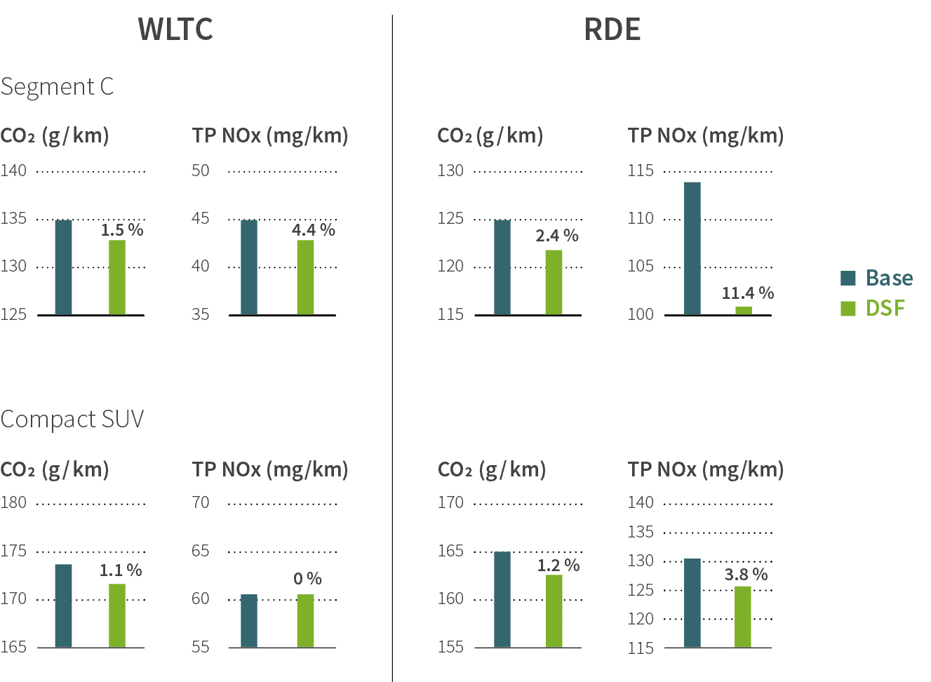
Figure 6 shows the simulation results of the MD truck application under cold stared WHTC. It can be seen, that the activation of DSF has increased the exhaust temperature upstream SCR by 10?–?30 K in a wide range of the cycle. Thus, an improved NOx
conversion has occurred and provided a tailpipe reduction by 15 percent compared to base configuration. Also fuel consumption benefit has achieved of around 1.6 percent due to the dynamic cylinder deactivation.
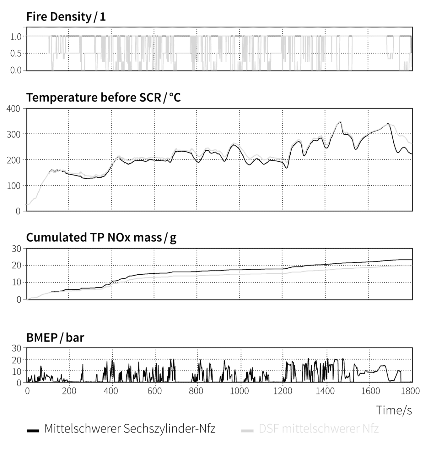
Figure 7 shows the summary results of MD truck in weighted WHTC. The weighting factors consider a distribution of 14percent cold started WHTC and 86 percent hot started WHTC.
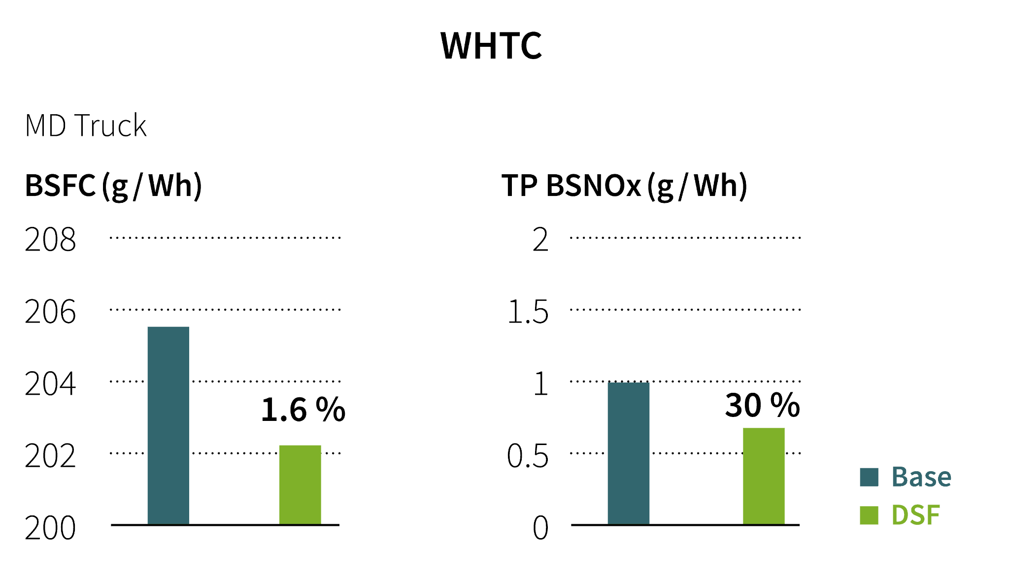
The investigations have shown a tailpipe BSNOx improvement of around 30 percent in parallel to BSFC benefit of 1.6 percent.


