6. May 2020
|

Over the past few decades, FEV has been involved in numerous large engine developments, ranging from high-speed and medium-speed to low-speed (2-stroke) engines. Based on this spectrum of experience, FEV has developed a completely new medium-speed engine family consisting of I6, I8, V12, V16, and V20 configurations, which cover a power range from 2 MW to 9.5 MW. A peak firing pressure capability of 250 bar and more than 70% communality of parts between all engine variants are two major enablers for achieving top ecological and economical ship operation.
Medium-speed engines for a variety of applications are facing several new challenges. Drastically reduced emission standards, especially for NOx, but in the future also for particulates, along with the requirements to simultaneously further reduce fuel consumption to comply with the Energy Efficiency Design Index (EEDE) CO2 targets, can only be met with advanced engine design concepts. From an economic point of view, newly developed engines have to consider fuel flexibility in order to be more independent of varying fuel prices and the availability of different fuel types. All of this must not compromise engine reliability, maintenance requirements and, of course, the cost of production.
The new medium-speed engine features a bore-to-stroke ratio of about 1.25 combined with a 45° cylinder bank angle for the V-type engines. This was found to offer the best balance between the anticipated power range, efficiency, compact engine package and weight. In addition, it covers a wide variety of possible applications, such as use with the coast guard or fire-fighting ships, tugs, various commercial vessels, emergency generator sets, onshore and offshore power plants, locomotives and others.
Provided by the 45° bank angle, a small engine width is mandatory—especially for locomotive applications, but also for the parallel installation of several engines in one application. The simultaneous development of the complete engine family ensured the highest possible modularity. The engine family setup for continuous operation in genset or main propulsion applications is equipped with a single-stage turbocharging system with the same turbochargers as the Inline 6 / V12 and Inline 8 / V16 engine versions. While the inline engines are fitted with one turbocharger, a setup utilizing two turbochargers was chosen for the V engines. One common charge air cooler housing for all V engines and one for the inline engine variants provides the turbocharger support. This complete charging system module can either be installed on the free end or on the flywheel side, depending on the installation requirements. For highest power output and intermitted peak power demands, sequential and double-stage turbocharging systems have been configured to ensure high acceleration performance at low speeds. The intake and exhaust manifolds are installed inside the Vee and on one side for the inline engine, whereas the camshafts with valve train and fuel injection equipment are installed outboard for the V engines and on the opposite side for the inline engines. This arrangement ensures the best possible accessibility for maintenance.
The camshaft assembly consists of common cam segments for all engine variants and bearing journals with different bolt patterns in order to ensure the correct timing. Eccentric shafts, supporting the cam followers, offer variable valve timing for intake and exhaust valves. Variable intake valve timing for Diesel / HFO and gas engines enables early inlet valve closure (Miller timing) for reduced NOx emissions at high load operation and later intake valve closure for better performance at low speed operation. Combined exhaust and intake valve timing variability facilitates cam overlap reduction for dual fuel engine variants in order to optimize gas admission to the cylinders. Hollow camshafts serve as the main oil gallery. This design solution avoids additional piping and increases torsional camshaft stiffness, which enables the installation of a conventional fuel injection system—especially for the dual fuel engine variant. Additional electronically controlled common rail injectors for small quantity pilot injections enable the ignition of the gas in gas mode operation. The Diesel and HFO engine variants are equipped with common rail fuel injection systems.
One common front-end module for all V engines and one for inline engines house the torsional vibration damper, the pipeless oil pumps, the high and low-temperature water pumps, the oil coolers and filters, the water and oil thermostats, and allow the installation of a support bearing in case of a hundred percent power takeoff on the free end. The hydraulically pressed-on crankshaft drive flange is common for all cylinder variants and for rear and front-end power takeoff. The oil and water pump drive gears are identical for all engine variants (inline and V), whereas the high pressure fuel pump drive is integrated in the camshaft gear train on the driving end of the crankcase. Due to the modular design, the inline engine gear train is realized as one half of the corresponding V engine gear drive.

Power range of the complete engine family
The complete cylinder unit is common for all engine variants. The vermicular or nodular cast-iron cylinder head contains four valves, actuated via two pushrods and guided valve bridges. The gas engine variant with a spark ignited pre-chamber combustion system uses the identical cylinder head design as the Diesel / HFO engine. The cylinder head for the dual fuel engine version requires only a different machining for the additionally required pilot injector, whereas the casting can stay unchanged.
Using gas as fuel for marine engines is a step forward when it comes to achieving good fuel efficiency combined with low exhaust emissions. For the gas engine variants, the Diesel fuel injector is being replaced by a multi-component pre-chamber. The upper part of this pre-chamber assembly is equipped with a top feed gas supply, including a mechanical passive check valve and the spark plug. The pre-chamber itself is located in the lower part of the assembly. A novel 3D CFD simulation methodology—Charge Motion Design (CMD) process—was applied, supported by experimental investigations on a single cylinder engine, in order to optimize the pre-chamber layout. The final experimental results showed high combustion stability, even with lean burn conditions, and demonstrated that BMEP levels significantly above the state-of-the-art level of more than 30 bar can be reached. Moreover, even with low-methane-number gas qualities, efficiencies above 45% were achieved while maintaining low HC emissions and, above all, NOx emissions below TA-Luft limits.
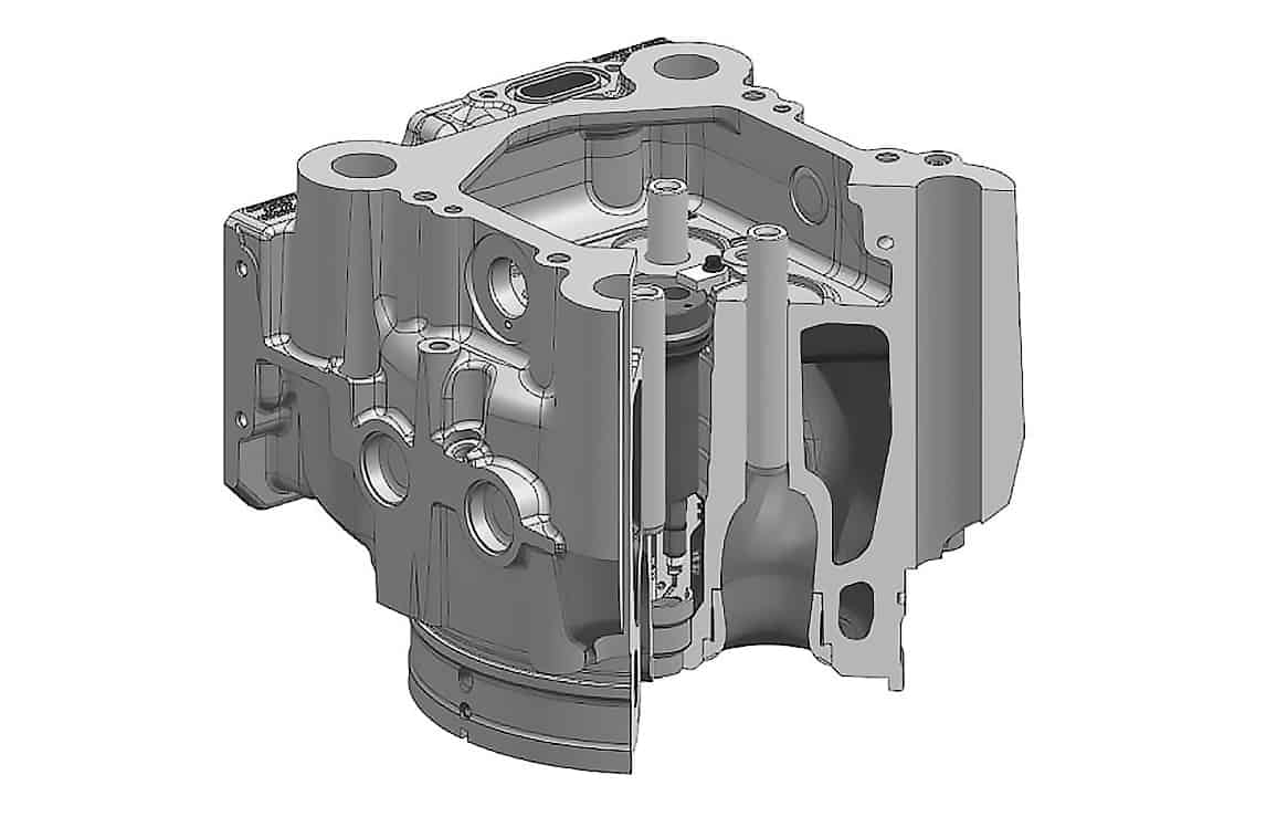
A mid-stop cylinder liner concept ensures optimized cooling at the top piston ring reversal point and the use of a carbon scraper ring enables long maintenance intervals. Due to separate liner housings for coolant supply to each cylinder, the complete crankcase can stay water-free, which avoids possible crankcase corrosion caused by bad coolant water treatment. The piston consists of a nodular, cast-iron skirt and a bolted steel piston crown. The conventional connecting rod with an inclined split line for the big end bearing cap enables a tighter engine package (width and height) compared to a marine type connecting rod design.
Intensive use of advanced simulation techniques, including fatigue analyses, dynamic analyses of valve train, gear train and complete engine assembly, fluid flow analyses, gas exchange and combustion simulation, and single cylinder engine testing were the enablers for a very efficient development process. A time schedule of about two years from project start to the validation of the combustion development for three different applications and emission standards, mechanical cylinder unit validation by functional testing on the FEV single cylinder engine and procurement as well as assembly of the first prototype engines (inline and Vee) is setting a new benchmark.
The Diesel / HFO engine family fulfils EU-Stage IIIA, EPA Tier3 emission standards for genset applications, IMO II for marine applications and EU Stage IIIA and EPA Tier 3 for locomotive applications with internal engine measures only and with very competitive fuel consumption, for engines in this speed range, of 183g/kWh. Depending on fuel availability and cost, meeting more stringent upcoming exhaust emission limits will be ensured with an additional SCR system for the Diesel / HFO engine variants or by switching to dual fuel or gas engine versions without any additional exhaust gas aftertreatment systems.
>> THE DIESEL AND HFO ENGINE VARIANTS ARE EQUIPPED WITH COMMON RAIL FUEL INJECTION SYSTEMS

Performance characteristics of the gas engine (single cylinder test results)
Gas engine cylinder head with spark-ignited pre-chamber (head identical with Diesel / HFO version)
>> A TIME SCHEDULE OF ABOUT TWO YEARS INCLUDING ASSEMBLY OF TWO PROTOTYPE ENGINES IS SETTING A NEW BENCHMARK


