6. May 2020
|

Increasing development efforts are anticipated to meet legislation targets, especially concerning the Euro 6d-TEMP particle number (PN) and nitrogen oxide (NOx) emission limits for DI gasoline engines under consideration of the upcoming real driving emissions (RDE) legislation. Vehicle manufacturers and developers primarily use so-called RDE cycles for emission quantification under real driving conditions. These cycles follow real driving situations and can often be considered representative of these. However, they do not offer the confidence of representing the “maximum” emission case for each vehicle-powertrain combination during the real driving operation. Therefore, their use is meaningful, but still insufficient with respect to a targeted and efficient emission development. FEV has addressed the issue of emission quantification under real driving conditions in the course of its continuous enhancement of the development process. The new methodology is capable of deriving the most challenging scenario regarding PN or NOx for any given vehicle-powertrain combination – the so called RDE Lead Scenarios.
In the face of the future tightening of the emission and CO2 legislation with simultaneously shortened development times and a high vehicle type variance, the methodology represents an essential building block for a targeted, efficient development. It offers a manageable, efficient procedure for the engineer at an early development stage which allows the optimization of the technology pack and ensures the compliance with the exhaust gas and CO2 emissions limits.

Overview of the four central segments of the FEV RDE Simulation
>> THE QUANTIFICATION OF VEHICLE EMISSIONS DURING THE DEVELOPMENT OFFERS A NEW DECISION MAKING CONFIDENCE
FEV’s RDE simulation supports development decisions in an early stage to ensure compliance with emission legislation limits. It is divided in four central segments, namely; (1.) definition of powertrain hardware including XCU strategies, (2.) emission modelling, (3.) parametric description of driver behavior and driving route and (4.) identification of the vehicle-powertrain-specific RDE Lead Scenario. This methodology is already applied at the beginning of the powertrain design process, and therefore offers a new decision making confidence through the quantification of vehicle emissions under real driving conditions during the development. The emission modelling is based on pollutant emission maps. This map-based approach is already known from CO2 emission modelling and considered being state of the art in this context. New raw emission models and exhaust gas aftertreatment models have been developed and implemented to facilitate the transfer of this concept to the highly complex pollutant emission modelling.
Real driving conditions have a very high variance compared to fixed driving cycles as NEDC or WLTC due to varying driver behavior, driving routes and ambient boundary conditions as traffic and weather. FEV has realized an abstraction of real driving conditions with the goal of the controllability of this high variance in terms of a time and cost-efficient development. The result of this work is a derivation of a concise number of parameters. This parameterization is essentially unlimited in its capacity. Optionally, it can be limited to RDE legislation, but it can also represent completely free driving situations.
During the identification of the vehicle-powertrain-specific RDE Lead Scenario, the parametric description of real driving situations allows the derivation of a multidimensional simulation space using DoE consisting of parametric combinations of driving scenarios and driving behavior (order of magnitude 1,000 scenarios), which covers all emission relevant driving situations which can occur in real operation.
Parametrization has been derived for:
>> FOR UNFAVORABLE COMBINATIONS, PN EMISSIONS ARE INCREASED BY A FACTOR OF 5 TO 10 COMPARED TO KNOWN CYCLES SUCH AS NEDC OR WLTC
FEV has used the described and validated development methodology during the development of a modern, turbocharged gasoline engine with direct injection that is used in a C segment vehicle.
A practical example shows the complexity and variety of an RDE test cycle and underlines the need for parameters which represent reality as good as possible. “The four parameters ‘vehicle speed’, ‘individual driver behaviour’, ‘ambient temperature’ and ‘average distance between two stops’ selected from a total of more than 10 parameters already have a significant influence on the PN emission in an RDE scenario,” explained Dr.-Ing Henning Baumgarten, Vice President Gasoline Engines. “For unfavorable combinations, PN emissions are increased by a factor of 5 to 10 compared to known cycles such as NEDC or WLTC.”
Appropriate measures regarding injection system and engine control strategies can reduce the PN emissions in the most challenging scenario in this case by 91 %.
“In this specific case, a late end of the last injection at engine start in the base configuration lead to a spontaneous run-up of the engine, but also to piston and wall wetting and a low mixture homogenization with local rich zones in the combustion chamber with corresponding high particulate formation”, explained Dr.-Ing. Matthias Thewes, Manager Thermodynamics Gasoline Engines.
The mixture could be prepared in a much more homogeneous way by using a new distribution for the injection quantities and optimizing the individual injection times. The PN emissions are reduced considerably. The emission results however show that the calibration measure in itself is insufficient to comply with the Not-To-Exceed Limit (Assumption: Euro 6d TEMP with CF = 2.1). In this example, a new layout of the injection system was examined as an additional measure. The combination of an optimized injection strategy with an enhanced injection system improved the mixture preparation and reduced the piston and wall wetting with fuel dramatically.
The Euro 6d-TEMP particulate limit is met without the use of a GPF. This is ensured by the use of the parameter combination with maximized PN emissions. However, since the PN result in the determined RDE Lead Scenario is in the range of the limit, a design protection for a GPF is recommended. The mirroring of ECU dataset adaptations, component selection and decisions on exhaust gas aftertreatment technologies with the help of the RDE Lead Scenario therefore offers the combination of confidence in the design during an early stage of development and a strong limitation of the variation space.
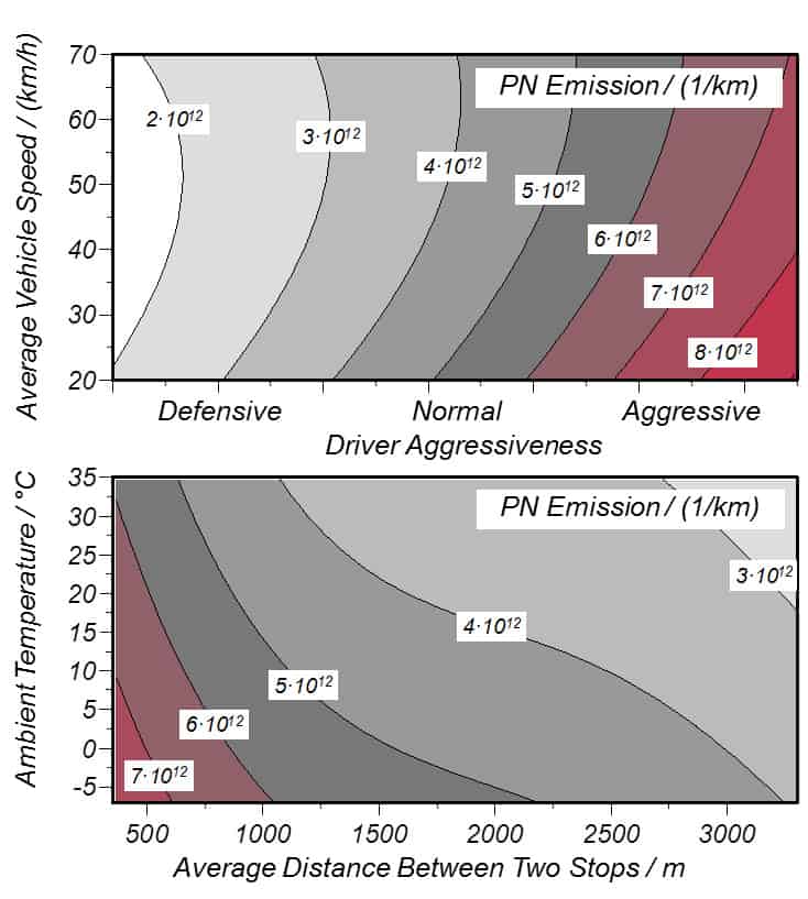
Correlation between selected scenario characteristics (DoE parameters) and PN emission: Average Vehicle Speed,
Individual Driver Behavior, Ambient Temperature and Average Distance Between Two Stops

Quantification of the influence of an optimized injection strategy on PN emissions
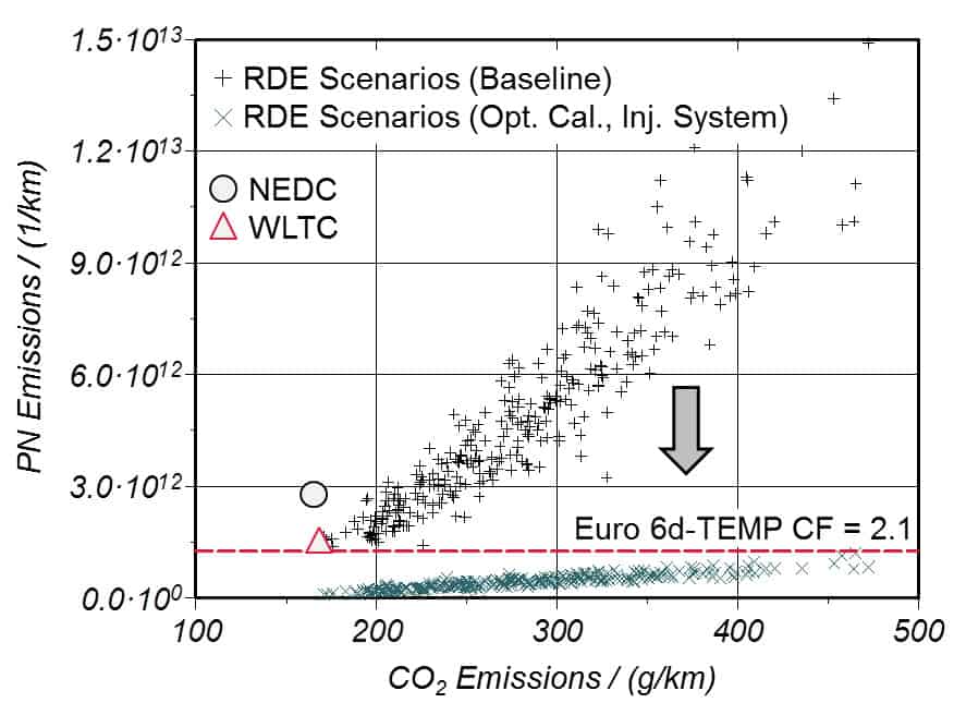
Influence of a new injection system with optimized injection strategy on PN emissions


