6. May 2020
|

The increasing tightening of global emission legislations promotes the further development of gasoline engines with the aim of clean engine operation under all real driving conditions. At the same time, performance requirements are growing. Gasoline engines compete increasingly with electrical components for package volume, and the displacement of high performance engines is reduced to lower the CO2 emissions. This article covers the trade-off between increasing specific power and switching to Lambda = 1 throughout the engine map.
Components in the exhaust gas flow of gasoline engines are currently protected from excessive thermal stress at high performance by mixture enrichment (Lambda < 1). At the same time, such an operating strategy is linked to the cross-influences:
The switch to Lambda = 1 leads to a loss of performance and reduces the specific power of current representative technology packages of gasoline engines to ~ 65 kW/L. It results in the increasing introduction of technological measures which improve the specific power at Lambda = 1. These include:
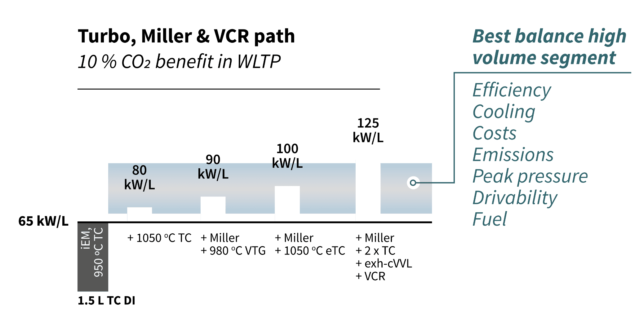
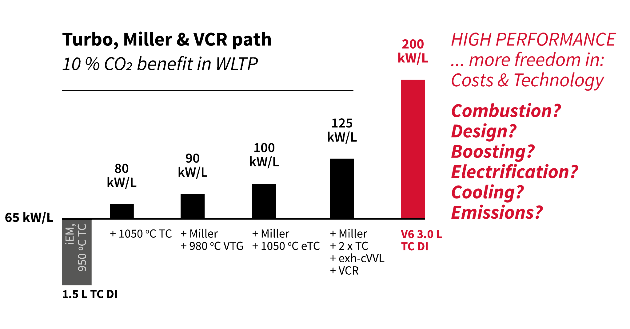
For volume segments from 85 to 100+ kW/L can well be achieved. The development of drive systems for high performance vehicles allows more freedom with regards to cost and applicable technology. FEV has investigated the following question: “Are 200 kW/L at Lambda = 1 possible?”
Combustion process for 200 kW/L at Lambda = 1
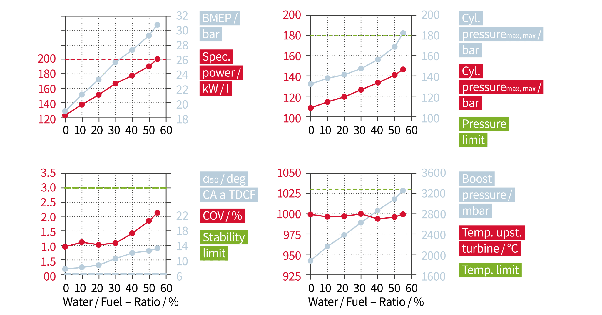
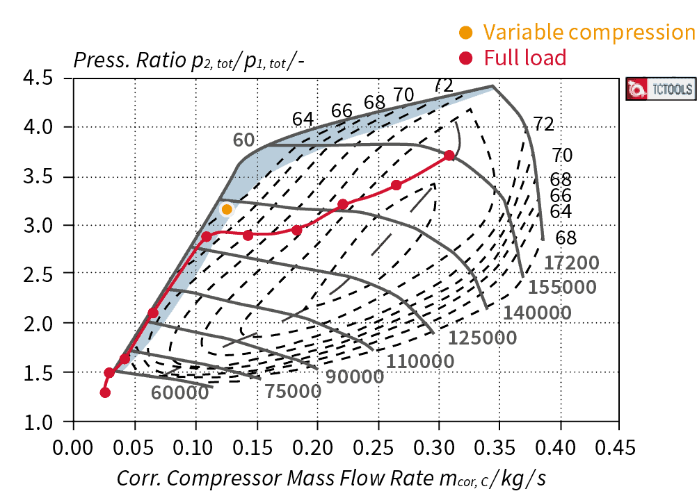
The realization of the specific power of 200 kW/L at Lambda = 1 requires a break-up of the conflict of interests between supercharging and knock tendency. Water injection in the intake port represents the key technology. The reduction of the mixture temperature associated with the high evaporation enthalpy of water at the end of compression allows for a significant increase of the efficiency of the high-pressure cycle. Figure 3 shows a variation of the water-fuel ratio (WFR) at a speed of 7800 min-1 and stoichiometric engine operation. With the selected compression ratio of 9.3:1 the brake mean effective pressure (BMEP) can be increased with the growing water share at only a slight delay of the center of combustion to 30.8 bar, so that the value of 200 kW/L is achieved at a WFR of 55 percent. An absolute boost pressure of approx. 3.3 bar is required, which can be supplied with a single-stage compressor.
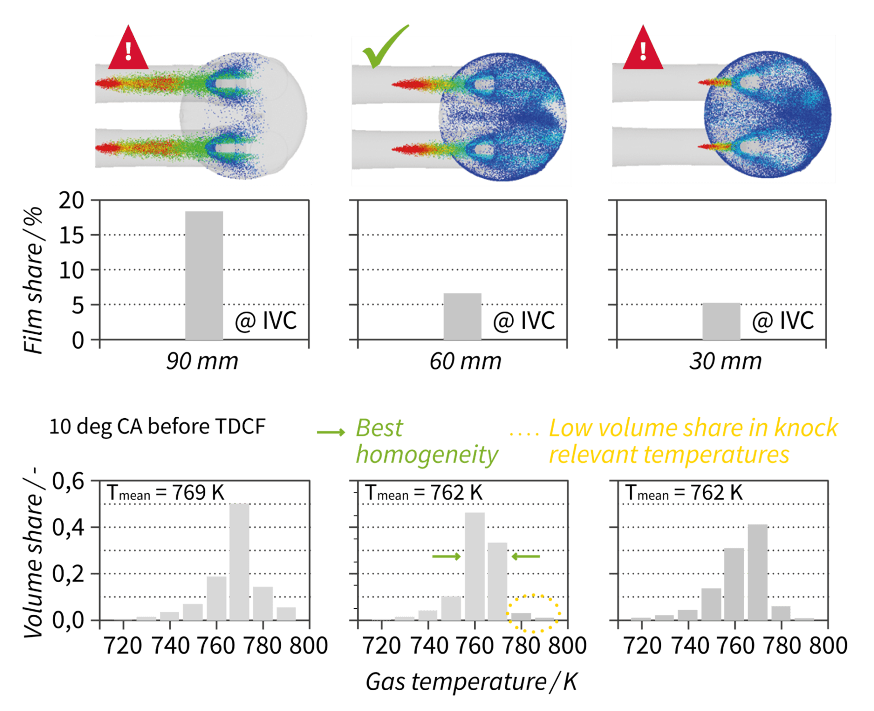
The position of the water injector in the intake port has been optimized with the help of 3D CFD simulations. For the distance that is furthest away from the valve, the wall film share is too high, because the water can wet the largest area. For water injection closer to the valve, the share decreases significantly, whereby the improvements for a distance of less than 60 mm are minor.
An analysis of the temperature distribution in the combustion chamber shows that the 60 mm position is preferable to the
30 mm position despite the same mean temperature.
With respect to the high mass flow rate and boost pressure demand, the requirement of a low throttle effect of the intake valves is in contrast to the objective of a high charge motion.
Figure 5 shows how 3D machined valve seat rings are used to achieve a high charge motion with simultaneously increased flow coefficient.

Design for high mechanical and thermal stress
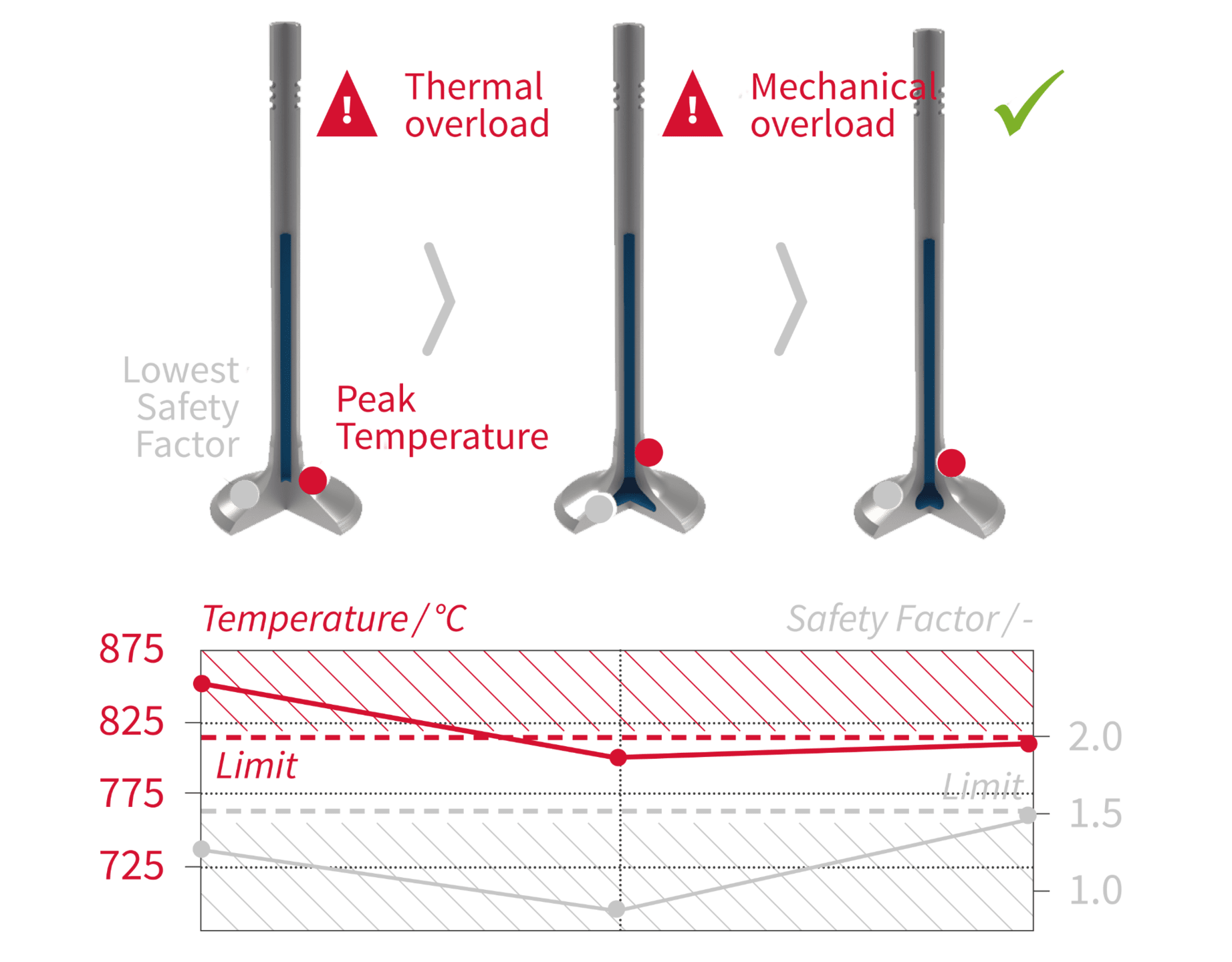
An engine design for a specific power of 200 kW/L must withstand high thermal stress and high mechanical load. The turbine wheel is manufactured from MAR 246 and withstands a maximum temperature of 1,050 °C. In addition to the exhaust gas turbocharger turbine, the exhaust valves are exposed to particularly high thermomechanical stress. Therefore, sodium-cooled exhaust valves are used. An optimized solution is used which directs the sodium into the valve disc and at the same time largely maintains its structure.
The aluminium cylinder block is a rigid closed-deck design with a bed-plate and cast iron cylinder liners. An aluminium spray coating guarantees a good connection between cylinder and crankcase. The high thermomechanical stress with the corresponding pronounced cylinder deformation is addressed with free form honing.

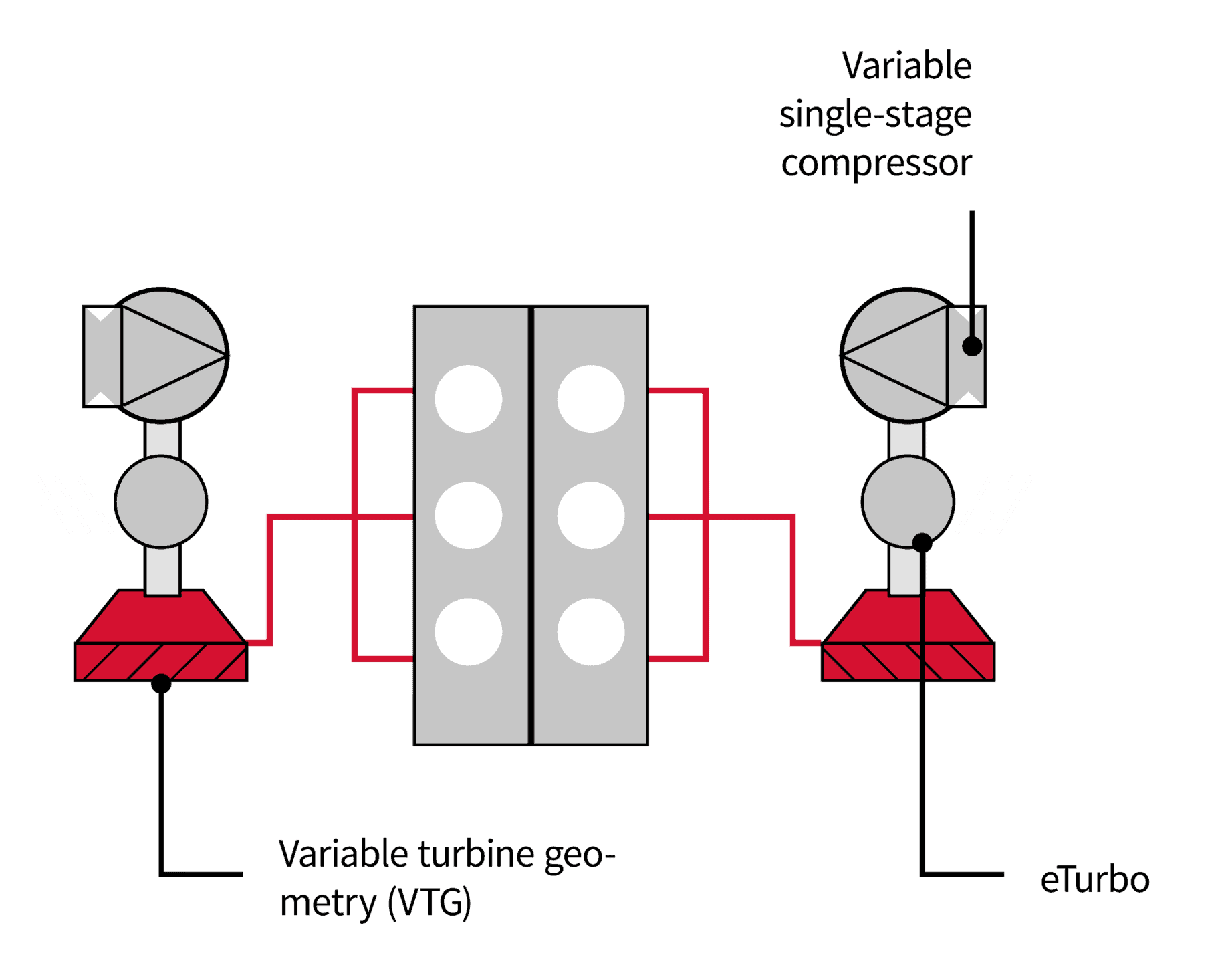
High performance boosting and periphery
The system is equipped with an exhaust gas turbocharger on each cylinder bank. The turbine is equipped with a variable turbine geometry without wastegate. The use of the entire exhaust gas mass flow for the generation of the compressor drive power lowers the turbine pressure ratio and therefore also the pressure upstream of the turbine. This means that lower gas exchange losses and exhaust gas temperatures can be reached at rated power.
Secondly, the added hot wastegate mass flow downstream of the turbine with the associated inhomogeneous thermal stress on the catalyst due to insufficient mixing is eliminated. The compressor is equipped with a variable trim, the turbocharger with an electric motor on the shaft to improve the transient behaviour.
Powertrain architecture and electrification
The high performance engine is embedded in the drive system. It consists of:
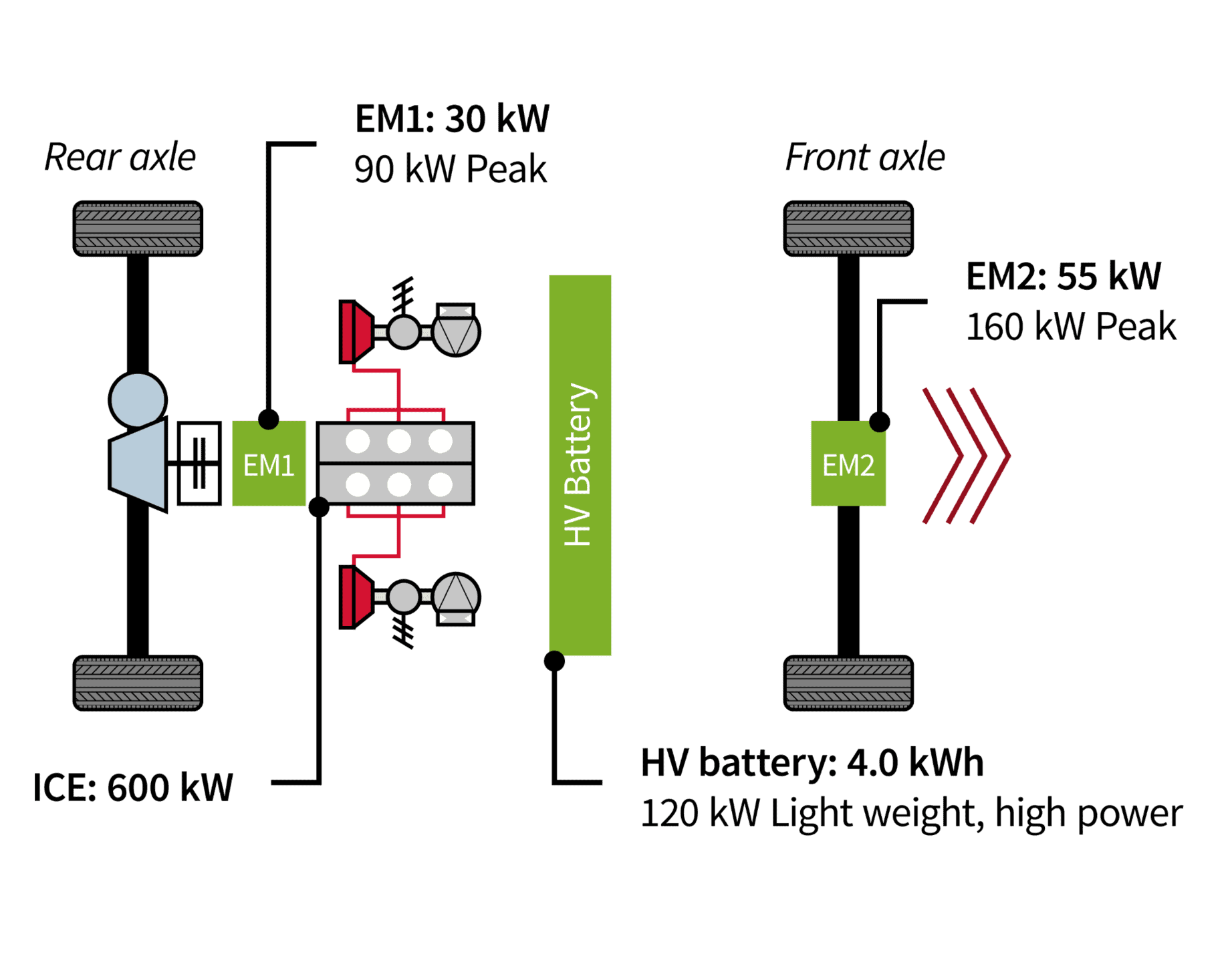
The combustion engine and the electric motor EM1 power the rear axle. The electric motor EM2 is configured as an electric drive unit. For reasons of weight reduction, the high voltage lithium-ion battery is designed as a small unit with a capacity of 4.0 kWh. At the same time, it delivers an output of 120 kW at a high C-rate of 30. The torque characteristics of all three engines are shown in Figure 10.
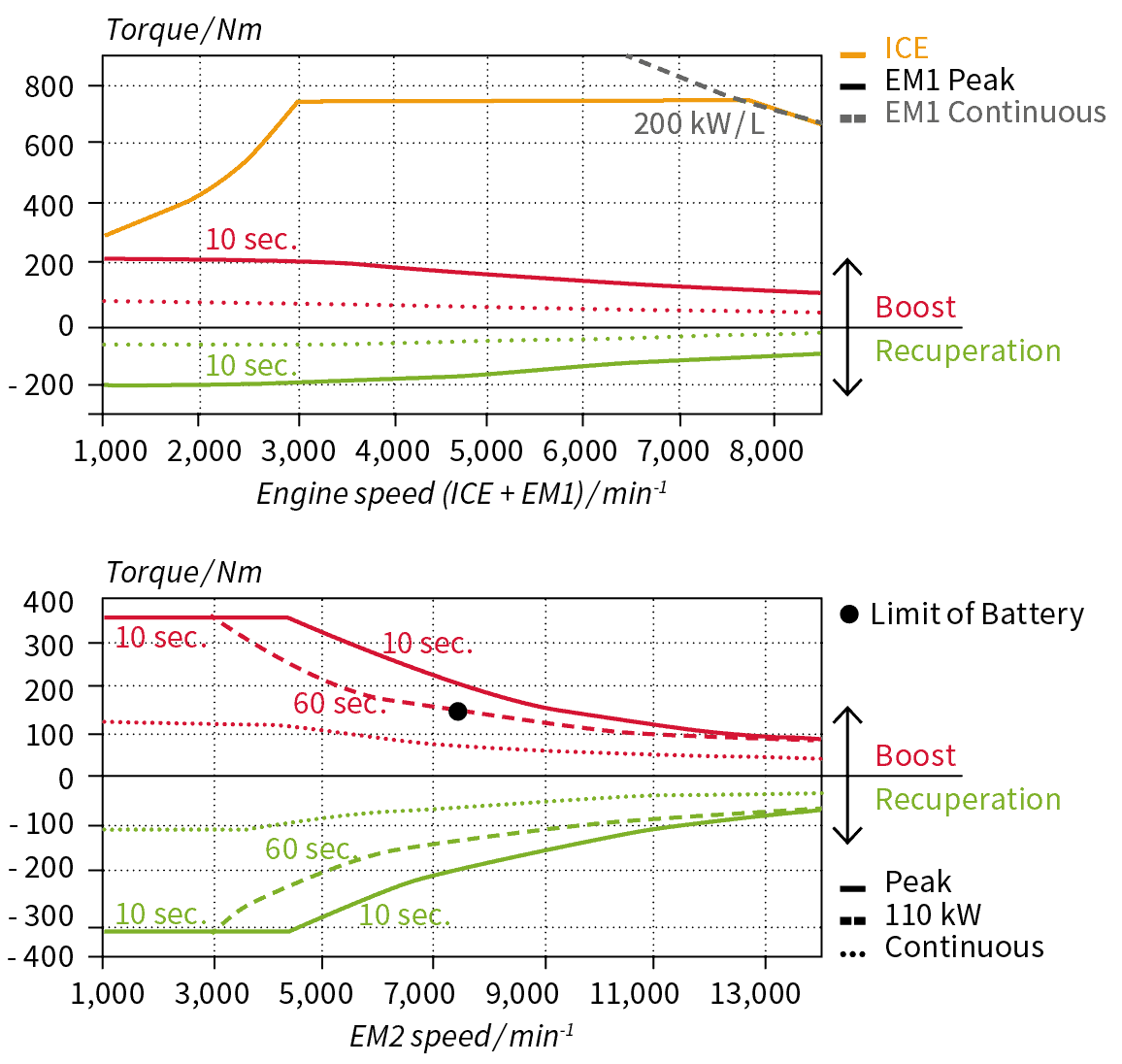
In high-speed range, the combustion engine is the dominant drive source. It delivers more than 85 percent of the total system power of 710 kW. The maximum speed is reached in the sixth gear and is limited to 350 km/h. Acceleration from 0 to 100 km/h is achieved without gear change in less than three seconds and is traction limited by the high torque at the rear axle. The operating strategy of the hybrid powertrain is illustrated using the example of the Nuerburgring race track (Figure 12). During braking and before a curve, the energy is recuperated. The acceleration out of a curve is supported by boosting with the EDU (EM2) at the front axle. All engines drive the vehicle on straight sections at full power demand.

Thermal management
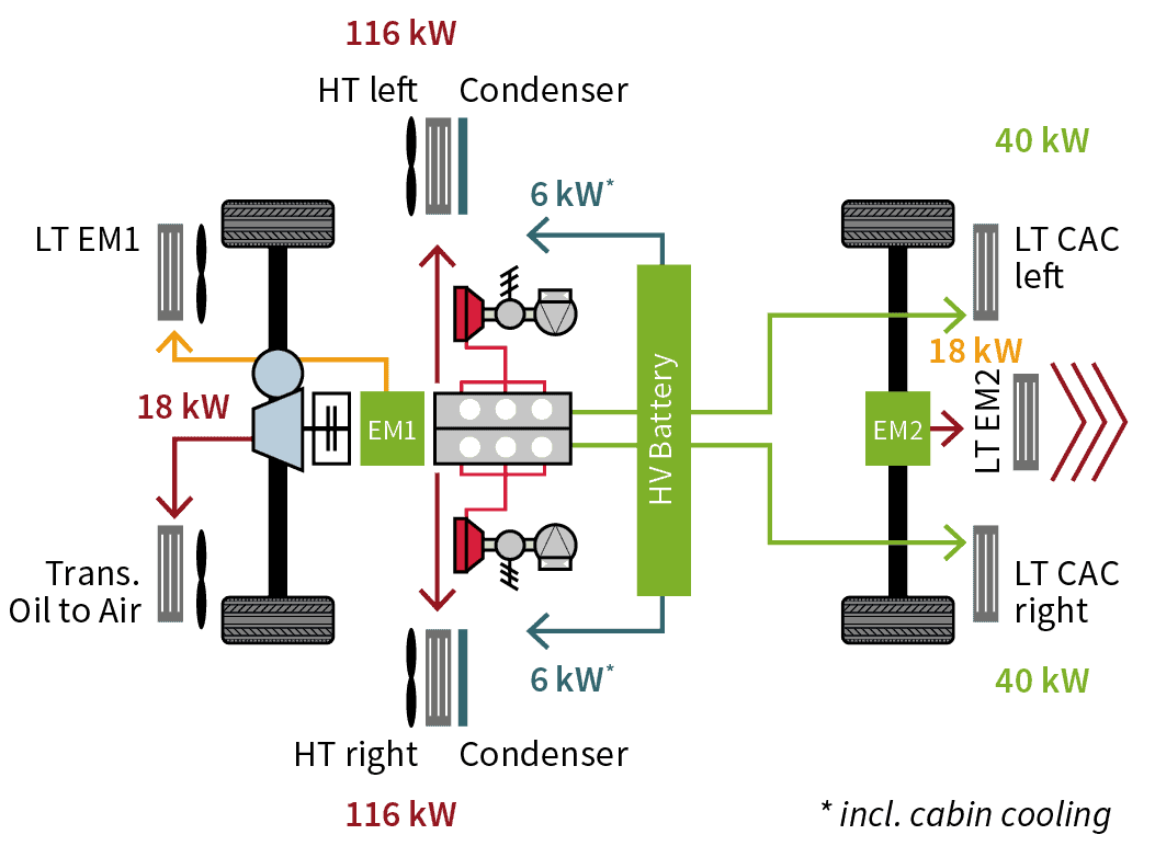
The cooling concept used here in the overall vehicle and the breakdown of the heat fluxes for a system power of 710 kW. The high temperature circuit (HT) of the engine cooling system needs to dissipate 232 kW. For this purpose, it uses two radiators integrated in the side pods. The transmission oil cooler transfers an additional 18 kW to the environment. The cooler for the low temperature circuit of the electric motor EM1 is located in the left rear wheel housing. The heat of the battery is transferred to a cooling circuit via an intermediate water circuit. The cooling circuit transfers the heat (6 kW) to the environment. A second condenser provides for the cooling need of the passenger cabin cooling. The heat of the cooling water of the air-water charge air cooler is transferred to the environment (in total 80 kW) through two low temperature coolers.
Emission control concept for Euro 7
The tightening of global emission legislations promotes the aim of low emissions operation under all driving conditions:
1 The restriction of the permissible particle number emission to 6 x 10¹¹ PN/km x CF under RDE conditions which was introduced with Euro 6d-TEMP.
2 The auxiliary emission strategies which receive less and less acceptance, and the discussion about the introduction of conformity for the pollutant CO under RDE conditions.
3 The significant reduction of the emission limits for gaseous pollutant to ~ 50 percent of the currently applicable Euro 6d-TEMP limits with the simultaneous restriction of CF = 1 expected with Euro 7, and the stricter focus on shorter driving distances after a cold start (< 10 km).

Figure 14 shows the exhaust gas aftertreatment system. The illustrated system is designed for one bank, and is mirrored for the second bank. The exhaust gas aftertreatment is equipped with one adsorber catalyst with a volume of 1.5 L per bank. Its ceramic substrate has a high heat capacity and stores HC emissions after a cold start until the light-off of the main catalyst has been reached. For the main catalyst, a metallic support material with low heat capacity and high heat conductivity has been chosen to reduce the light-off time. The volume of the main catalyst is 3.5 L per bank without adsorber catalyst and without particulate filter. Two electrically heated discs per bank have been integrated into the main catalyst. A coated particulate filter (4WC) with a volume of 4.0 L follows downstream of the catalyst.


