6. May 2020
|

The trend towards battery electric vehicles will continue and likely even accelerate in the future. These vehicles will make a significant contribution to meet future targets for fleet fuel consumption and emissions. To be commercially successful, these new vehicles require modern and intelligent solutions for their powertrain, including battery and drive unit.
The optimal drive unit concept has to be developed based on an evaluation of performance, efficiency, and cost on a system level, including all powertrain components, such as a battery, inverter, electric motor, and transmission. This is what FEV and YASA have done with a high-performance D-class passenger car application in mind. The result is a drive unit concept with exceptional power density and efficiency based on YASA’s unique axial flux motor technology and an innovative 2-speed transmission concept by FEV.

Figure 1 shows an external view of the drive unit and its main specifications. With a peak of power of 300 kW and a weight of less than 85 kg, it provides an outstanding power density of 3.5 kW/kg on system level. The maximum axle torque of 6.00 Nm even exceeds typical wheel slip limits for both front and rear-wheel drive applications and ensures superior acceleration performance on a vehicle level.
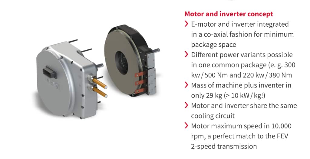
Electric motor and inverter
The YASA motor is an axial-flux permanent magnet machine and was chosen because of its high power density (up to 15 kW/kg for custom motor designs), high efficiency (especially at part loading) and low-cost manufacturing. In the YASA motor, the oil coolant is in direct contact with the copper windings, providing very efficient and even cooling over each winding.
YASA controllers feature similarly differentiated high-density performance. This is achieved by the use of some of the YASA motor’s proprietary direct oil cooling technologies that provide for very efficient cooling, and substantially reduce the need for heavy and costly heatsinks and power semiconductor packaging. When integrated with a YASA motor, the motor and controller share the same oil cooling circuit, further improving the standard integration benefits of reduced volume, mass and interconnection complexity.
Gearset concept
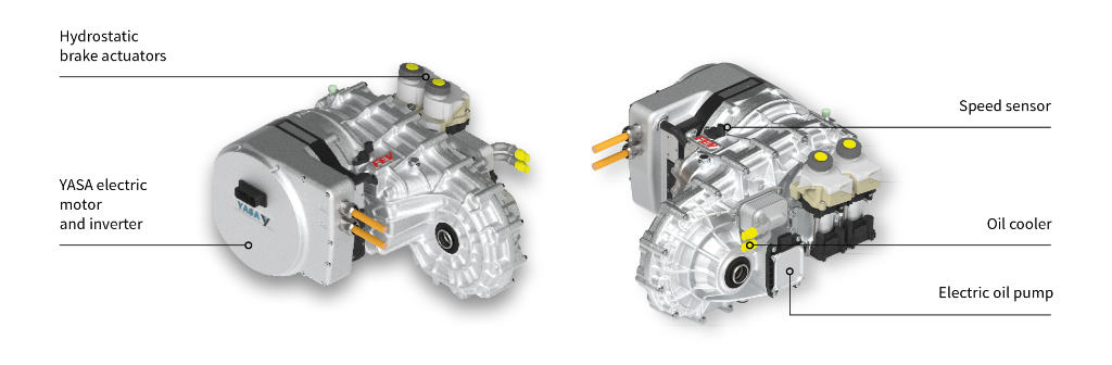
Based on the above-mentioned findings, a powershift capable 2-speed concept was developed. Figure 3 shows different views of the drive unit.
The 2-speed functionality is realized based on a Ravigneaux planetary gearset. Figure 4 explains the topology of the transmission. The planetary gearset is arranged coaxially to the electric motor. The small sun (SS) does serve as the input, and the ring (R) serves as the output to the intermediate shaft and differential. Two brakes B1 and B2 are used to realize two speeds. Brake B1 is connected to the carrier and paired with a one-way clutch (OWC), B2 is connected to the large sun gear (SL). Despite being mechanically more complex than architectures in a simple planetary gearset, this architecture has a number of technical benefits. As shown in the table “Clutch relative speed matrix”, the delta speed at open brakes is always below the input speed at the small sun, an important quality for minimum drag losses. At the same time, the torque reaction at the brakes is favorable as shown in the table “Clutch torque matrix”. Brake B2 only has to react less than half of the input torque. Brake B1 has to react 1.5 times the input torque but is supported by the one-way-clutch. This allows to size the brake itself smaller, further reducing drag losses. As opposed to clutches, brakes avoid the use of rotary joints or engagement bearings to actuate the gearshift. In addition, the thermal capacity of brakes can be scaled via the thickness of their (stationary) steel lamellae without negatively affecting rotary mass moments of inertia. The exclusive use of brakes was, therefore, an important criterion in the selection of the concept. Both brakes are actuated via an existing series-production, on-
demand actuator from LuK. The unit, also known as HCA (hydrostatic clutch actuator), operates with a brushless electric motor for each gearshift element, which actuates a hydraulic master piston via a spindle. Because of the leakage-free seals, this system is very efficient. Alternatively, electromechanical actuation concepts could be used thanks to the good axial accessibility of the brakes.

Figure 5 summarizes the functions of both the brakes and the one-way clutch. It also mentions an additional advantage of the arrangement, including the one-way clutch: In 1st speed during drive (power-on) condition, B1 can be opened and the reaction torque at the carrier will only be provided by the one-way clutch. Then, the power-on upshift, which is most critical in terms of shift comfort, can be performed by only closing brake B2. This type of shift is easier and more robust than any conventional power shift which typically includes the simultaneous control of two shift elements. The same advantage applies to a power-on downshift when only B2 has to be opened. At zero rpm of the carrier, the one-way clutch will automatically lock-in and engage 1st speed.

Cooling and lubrication concept
As mentioned previously, the electric motor and inverter do share one common oil cooling circuit. Using a dedicated EDU oil which fulfills the requirements of both the electrical and mechanical components, also allows for the transmission to be integrated into that cooling circuit. As of today, such a fluid is not yet readily available, however, several oil suppliers have confirmed that it can be successfully developed within a standard series development of 3 years duration. The obvious advantage of such a highly integrated cooling and lubrication circuit is less complex and more cost-effective, as only one pump, one cooler, and almost no external hosing would be required. In addition, the interfaces to the vehicle would be simplified considerably. Alternatively, separate oil circuits can be used for the electric motor/inverter and transmission. In this case, oils are readily available and can be tailored even better for the requirements of each circuit. The development risk will be reduced, but the complexity and cost of the overall system will be increased.
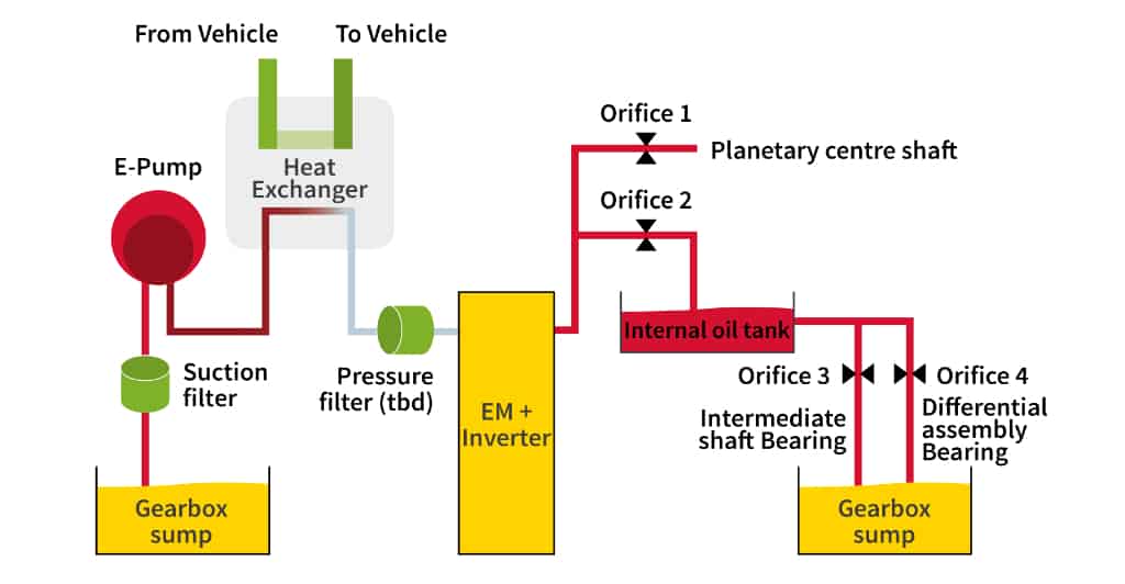
Figure 6 explains the variant with one common cooling and lubrication circuit. An electric oil pump draws oil out of the transmission sump and feeds it via an oil/water heat exchanger to the inverter. From there, the oil flows through the electric motor and subsequently back into the transmission, where the volumetric flow is divided. One part is fed into the main shaft of the planetary gear set, from where it not only lubricates the gears and bearings but also cools the brakes as required. The remainder is not drained into the sump but buffered in a storage tank inside the transmission. From here, further components are lubricated via various channels, including the gear meshes and the bearings of the intermediate shaft.
An intelligent oil pump control strategy allows to vary the level of the storage tank and thus the oil level in the transmission, which makes a large contribution to a reduction in churning losses and thus an increasing inefficiency. Figure 7 shows two internal views of the transmission including the integrated oil reservoir. A park lock system is arranged on the intermediate shaft and can be actuated by a stand-alone, electro-mechanical park-by-wire actuator.

Summary
The presented 2-speed drive unit does use a high powered, dense yet modular combination of an axial flux electric motor and a coaxially arranged inverter. The transmission is based on a Ravigneaux planetary gearset with two brakes as the shift elements. Together, with a one-way clutch, this arrangement is both favorable in terms of drag losses, as well as controllability and shift comfort. The brakes are actuated on-demand for minimum energy consumption. The electric motor, inverter, and transmission do optionally share a single, common cooling and lubrication circuit which reduces complexity and simplifies the interfaces of the drive unit to the vehicle. With a peak power of 300 kW and a weight of less than 85 kg, the drive unit provides an outstanding power density of 3.5 kW/kg on system level. The maximum axle torque of 6,000 Nm even exceeds typical wheel slip limits for both front- and rear-wheel drive applications and ensures superior acceleration performance on vehicle level.
Final remark
The drive unit concept presented in this article has been jointly developed by YASA and FEV. The motor and inverter technology described in this paper is owned by YASA Limited, a UK-based developer and manufacturer of electric motors and inverters. The 2-speed transmission concept described in this paper is owned by FEV, an independent provider of powertrain and vehicle engineering services.


