6. May 2020
|

Battery management systems (BMS) are necessary for the precise monitoring and control of the key component in electric vehicles – the lithium-ion battery. Since 2006, FEV has been involved in the development of battery management systems and, with its experienced team, is a partner of choice for hardware and software development for BMS. The portfolio offered by FEV ranges from the development of individual complex software functions, such as State of Health (SoH) and the provision of a BMS development environment for research purposes, up to turn-key development of a complete, client-specific BMS solution including a necessary, functional safety concept. Here, the serial production-ready FEV BMS software and the proven FEV BMS hardware can be relied on. The uniqueness about this software and this hardware is that both black-box and white-box solutions can be made available.
The performance capability of batteries is influenced by the quality of the control in addition to the selection of suitable battery cells. For the battery management system, which is one of the core systems with regard to battery development, FEV started developing its own BMS control units as early as 2006 and now has its own modular BMS system in the fourth generation, which, depending on the project requirements, can be implemented efficiently, as well as combined in different ways. This includes the battery management unit (BMU), various cell monitoring units (CMU) for 12, 15 or 18 battery cells, as well as the isolation monitoring unit (IMU). In this context, the BMU is the central unit, which controls the CMUs, the decentralized measurement units.
With the development and protection activity in many projects with a variety of requirements and battery architectures, the hardware components have a B-sample degree of maturity and, in addition to use in prototypes, can be purchased as a white box for serial development. During this continuous development, the availability of the installed components is just as much a focal point as the technical maturity, whereby the topic of obsolescence management is also taken into consideration.
The fifth generation of hardware is currently in an advanced development phase. This generation is suitable, for instance, for installation in battery systems from 48 V to 800 V. Batteries with one or several strands, as well as switchable 400 V/ 800 V batteries, can be controlled and monitored with this. Another advantage of the fifth generation is the four CAN communication channels, as well as the support from CAN-FD, the wake-up via CAN and partial networking. In addition to CAN, the BMU has two LIN channels as well as many inputs and outputs in order to meet the various client requirements. Customized development as per client requirements for serial use is also part of the portfolio.
An individual CMU from FEV monitors the temperature and voltage of up to 18 battery cells. Thanks to our proprietary hardware development and the simple, modular design, the CMU can be rapidly adjusted for the development process of various battery configurations with little effort. During development, the topic of cost optimization was also considered. In this context, a decrease in components, such as plugs, as well as a reduction of the test and manufacturing effort is pursued.
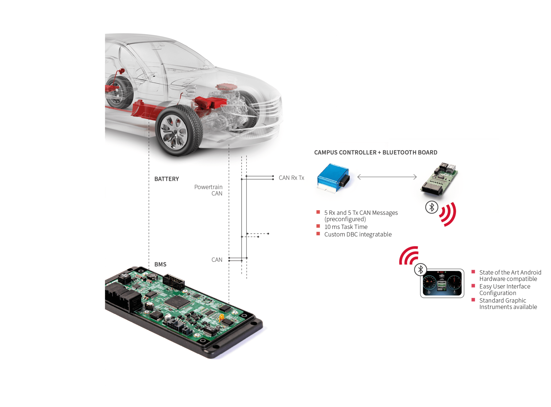
For the development phase, with the Campus Controller, FEV has developed a freely programmable control unit that can take over the various functions of the BMS or other control units, including:
In combination with the FEV “VISION” project, a Bluetooth-based visualization solution, the system is a high-performance tool for various development purposes.
In this project, FEV focuses on the topic of man-machine interface for prototype vehicles. On the one hand, “VISION” is made up of the real time-compatible CAMPUS hardware, which takes over CAN gateway functions in this context and, on the other hand, of a tablet with the corresponding app. The CAMPUS hardware takes over the role of the cybersecurity gateway and connects the CAN network of the battery or the vehicle via a Bluetooth interface with the tablet. This ensures that only the relevant messages are read or sent. The data connection is implemented bi-directionally so that, on the one hand, the relevant system information, such as the charge status of the battery, the power requirement and the rotational speed of the engine, can be displayed on the tablet and, on the other hand, so that the commands from various input instruments (e.g. buttons or sliders) can be sent to the vehicle control units. Using the wireless connection, the tablet can also be outside the vehicle for presentation purposes or handed over to interested parties in order to share technical data during test drives.
It is also possible to exchange information with internet servers and thus record measured data – for instance, using the internet connection of the tablet hardware.
The software of a battery management system is crucially important to the performance of the battery throughout the entire life cycle and has a direct influence on central characteristics of the vehicles – for instance, on the range for purely electric driving modes (PHEV, BEV). Furthermore, the BMS often takes over functions, such as charging times forecasts or the calculation of the available power, which can be seen directly by the client, thereby influencing the vehicle experience. A precise calculation of parameters, such as the State of Charge (SoC) as well as the State of Health (SoH), is the basis for an optimal exploitation of the battery system and is simultaneously very challenging, because these are values that cannot be measured directly. Furthermore, the software is an important component of the safety mechanisms that ensure the safety of the battery system during operation.
The FEV BMS software has been continuously developed since 2006 and, thanks to a modular architecture with lean, AUTOSAR-compatible interfaces, can be used with various BMS systems flexibly and with little effort. Thus, this software is already being used for various battery systems, from small 12 V and 48 V systems up to high-voltage batteries with flexible wiring options. FEV relies here on broad experience, since many projects require fulfilling the individual requirements of the respective client. These requirements arise, for instance, from differences in the E/E layout or the architecture of the battery or from the functional integration into the vehicle. Fundamentally, the software is divided into three components: application, safety, and base software.

The FEV BMS application software is developed in a model-based manner and includes features such as power/current release, charge regulation, SoC/SoH calculation, balancing, contactor control, and battery diagnoses. The software is used on both the FEV BMS hardware and the control units of client suppliers. The porting of the application software to other platforms has already been carried out in several (serial) projects and the interface has thus been continuously optimized in order to keep the adjustment effort as low as possible. This also applies to interfaces to the vehicle. All relevant values can be parameterized or calibrated; this is another decisive factor with regard to the flexibility of the software. Particular attention is paid to the topic of verification and validation of the software. Here, test methods and tools of the FEV Embedded System Test Center (FEST) are relied on, along with HIL test system for battery management systems, which can emulate up to 192 individual cells.

The FEV BMS base software represents a development for FEV’s own BMS hardware. The software achieves the connection to the hardware components of the BMU and the CMUs, as well as provides the application software with, for instance, the storage of values in a “non-volatile memory” along with measurement values and I/Os for various services.
In addition to the development of the BMS software, FEV also supports OEMs and suppliers in developing their own BMS application and/or base software.
The functional safety concept can be developed either for a specific vehicle or as a stand-alone product independent of any vehicle (“off-the-shelf components”). If the development is for a known vehicle, the development of the battery system is directly integrated in the FuSa life cycle of the overall vehicle. This is normally the case for FEV developments. In contrast, if the development takes place independently of any vehicle (“safety element out of context”), a portion of the FuSa overall life cycle for the battery is observed. The integration in the overall vehicle life cycle then takes place at a later point by the vehicle manufacturer. The assumptions must be reviewed with regard to validity and any necessary changes must be processed via change management.
“THE FEV BMS APPLICATION SOFTWARE IS DEVELOPED IN A MODEL-BASED MANNER”
Considered aspects
Functional safety deals with risks that may be triggered by potential malfunctions of E/E systems due to systematic software or random hardware errors. In order to develop the battery system in a sufficiently safe manner according to current standards, FEV complies with the development principles of the ISO 26262 standard. Certain hazards, such as those due to chemical hazards or electric shock, are only considered part of the functional safety if the hazard is directly caused by the E/E function. Applied to the battery system, this means that the prevention of electric shock is primarily covered by the high-voltage safety. HV insulation and touch protection therefore does not fall within the scope of functional safety. However, certain E/E functions can also serve high-voltage safety and, accordingly, fall within the scope of functional safety. This is the case for an HV system switch-off during an accident, since here, the measures taken by HV safety, such as insulation, may be damaged and therefore can no longer be considered sufficient.
Concept phase
During what is known as the concept phase, there is an assessment of the risks that could occur due to malfunctions in the implemented system functions. In the process, FEV follows the approach described in the figure. The result of this hazard analysis and risk assessment (HARA) is the safety goals for the system. The scope of the necessary risk reduction is determined by the ASIL, leading to a classification using the letters from A to D. A typical example of a safety goal for a battery system is “The system should prevent battery thermal runaway” (typically rated by FEV with ASIL C or ASIL D). These safety goals are top-level requirements. Based on these safety goals, a functional safety concept is developed which is described in the functional safety requirements. In addition to detection, the safety concept also includes the emergency measures to be initiated. The creation of the functional safety concept is frequently complemented by failure tree analyses.

Product development phase
The system development phase comes after the concept phase. In this phase, the functional requirements are translated into technical requirements. Accordingly, this step is carried out together with the development of the technical system architecture. During this phase, depending on the ASIL classification of the safety goals, failure tree analyses and FMEAs are required by the ISO26262 standard. This phase then leads to the HW and SW development phases, with the safety requirements being incorporated into these phases.
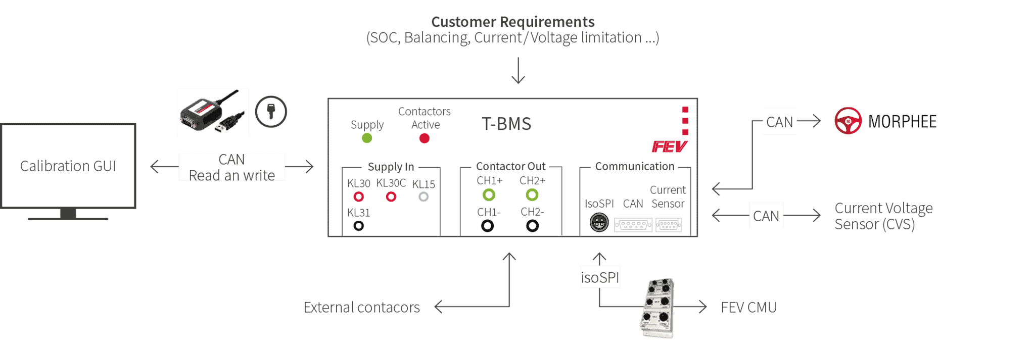
The battery management system from FEV is also suitable for other applications, such as utilization on the test bench.
To this end, FEV has developed a universal BMS (T-BMS) for battery modules; an expansion for the testing of entire batteries is also possible.
The system is based on an FEV BMU and one or several FEV CMU(s), serving to record cell parameters and their monitoring, as well as to calculate other parameters such as State of Charge (SoC). In this context, client-specific functions for the calculation of the necessary parameters can be implemented in the T-BMS. All entered parameters can be transferred to the test bench in order to record, analyze, and utilization for the test procedure. The T-BMS can naturally be used with FEV battery test benches as well as FEV MORPHEE, which enables us to offer a complete solution (see page 30) for the testing of battery modules. Thanks to the easily adjustable CAN interface, however, the T-BMS can also be utilized with a variety of other test benches.
Via a graphical user interface it is possible to calibrate all essential
parameters of the system, such as the number of connected cells. This allows a simple adaptation to different test requirements.